

Bar electrodes, welding rods and more
Services of Bremer Schweißtechnik GmbH
Bar-electrodes
Our range of products:
- for non-alloyed and low-alloyed-steel
- for creep resistant- and tube-steel
- for fine-grained-steel for structural use and special constructional steel
- for stainless steel
- for heat-resistant steel
- for high-temperature steel
- for low-temperature steel
- for austenite-ferrite-compounds
- for overlays
- for aluminium welding
- for nickel-based alloys
- for underwater-welding und -cutting
-
Arc welding
Arc welding
Arc welding uses a welding power supply to create an electric arc between an electrode and the base material to melt the metals at the welding point. They can use either direct (DC) or alternating (AC) current, and consumable or non-consumable electrodes. The welding region is sometimes protected by some type of inert or semi-inert gas, known as a shielding gas, and/or an evaporating filler material. The process of arc welding is widely used because of its low capital and running costs.
Development
While examples of forge welding go back to the Bronze Age and the Iron Age, arc welding did not come into practice until much later. In 1800, Humphry Davy discovered the electric arc, initiating the development of arc welding which continued with the inventions of metal electrodes by a Russian (N.G. Slavianoff) and an American (C.L. Coffin) in the late 1800s even as carbon arc welding, which used a carbon electrode, gained popularity. Around 1900, A. P. Strohmenger released in Britain a coated metal electrode which gave a more stable arc. In 1919, alternating current welding was invented by C.J. Holslag but did not become popular for another decade.
Competing welding processes such as resistance welding and oxyfuel welding were developed during this time as well, but both, especially the latter, faced stiff competition from arc welding especially after metal coverings (known as flux) for the electrode, to stabilize the arc and shield the base material from impurities, continued to be developed. During the surge in the use of welding caused by World War I, arc welding became even more popular as the British constructed a ship, the Fulagar, with an entirely welded hull. The Americans also became more accepting of the new technology when the process allowed them to repair their ships quickly after a German attack in the New York Harbor at the beginning of the war. Arc welding was first applied to aircraft during the war as well, and some German airplane fuselages were constructed using this process.
During the 1920s, major advances were made in welding technology, including the 1920 introduction of automatic welding in which electrode wire was continuously fed. Shielding gas became a subject receiving much attention as scientists attempted to protect welds from the effects of oxygen and nitrogen in the atmosphere. Porosity and brittleness were the primary problems and the solutions that developed included the use of hydrogen, argon, and helium as welding atmospheres. During the following decade, further advances allowed for the welding of reactive metals such as aluminum and magnesium. This, in conjunction with developments in automatic welding, alternating current, and fluxes fed a major expansion of arc welding during the 1930s and then during World War II.
During the middle of the century, many new welding methods were invented. Submerged arc welding was invented in 1930 and continues to be popular today. Gas tungsten arc welding, after decades of development, was finally perfected in 1941 and gas metal arc welding followed in 1948, allowing for fast welding of non-ferrous materials but requiring expensive shielding gases. Using a consumable electrode and a carbon dioxide atmosphere as a shielding gas, it quickly became the most popular metal arc welding process. In 1957, the flux-cored arc welding process debuted in which the self-shielded wire electrode could be used with automatic equipment, resulting in greatly increased welding speeds. In that same year, plasma arc welding was invented. Electroslag welding was released in 1958 and was followed by its cousin, electrogas welding, in 1961.
Power supplies
To supply the electrical energy necessary for arc welding processes, a number of different power supplies can be used. The most common classification is constant current power supplies and constant voltage power supplies. In arc welding, the voltage is directly related to the length of the arc, and the current is related to the amount of heat input. Constant current power supplies are most often used for manual welding processes such as gas tungsten arc welding and shielded metal arc welding, because they maintain a relatively constant current even as the voltage varies. This is important because in manual welding, it can be difficult to hold the electrode perfectly steady, and as a result, the arc length and thus voltage tend to fluctuate. Constant voltage power supplies hold the voltage constant and vary the current, and as a result, are most often used for automated welding processes such as gas metal arc welding, flux cored arc welding, and submerged arc welding. In these processes, arc length is kept constant, since any fluctuation in the distance between the wire and the base material is quickly rectified by a large change in current. For example, if the wire and the base material get too close, the current will rapidly increase, which in turn causes the heat to increase and the tip of the wire to melt, returning it to its original separation distance.
The direction of current used in arc welding also plays an important role in welding. Consumable electrode processes such as shielded metal arc welding and gas metal arc welding generally use direct current, but the electrode can be charged either positively or negatively. In welding, the positively charged anode will have a greater heat concentration and, as a result, changing the polarity of the electrode has an impact on weld properties. If the electrode is positively charged, it will melt more quickly, increasing weld penetration and welding speed. Alternatively, a negatively charged electrode results in more shallow welds. Non-consumable electrode processes, such as gas tungsten arc welding, can use either type of direct current, as well as alternating current. With direct current however, because the electrode only creates the arc and does not provide filler material, a positively charged electrode causes shallow welds, while a negatively charged electrode makes deeper welds. Alternating current rapidly moves between these two, resulting in medium-penetration welds. One disadvantage of AC, the fact that the arc must be re-ignited after every zero crossing, has been addressed with the invention of special power units that produce a square wave pattern instead of the normal sine wave, eliminating low-voltage time after the zero crossings and minimizing the effects of the problem.
Consumable electrode methods
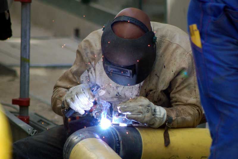
One of the most common types of arc welding is shielded metal arc welding (SMAW), which is also known as manual metal arc welding (MMA) or stick welding. An electric current is used to strike an arc between the base material and a consumable electrode rod or 'stick'. The electrode rod is made of a material that is compatible with the base material being welded and is covered with a flux that protects the weld area from oxidation and contamination by producing CO2 gas during the welding process. The electrode core itself acts as filler material, making a separate filler unnecessary. The process is very versatile, requiring little operator training and inexpensive equipment. However, weld times are rather slow, since the consumable electrodes must be frequently replaced and because slag, the residue from the flux, must be chipped away after welding. Furthermore, the process is generally limited to welding ferrous materials, though specialty electrodes have made possible the welding of cast iron, nickel, aluminium, copper and other metals. The versatility of the method makes it popular in a number of applications including repair work and construction.
Gas metal arc welding (GMAW) is a semi-automatic or automatic welding process that uses a continuous wire feed as an electrode and an inert or semi-inert shielding gas to protect the weld from contamination. When using an inert gas as shield it is known as Metal Inert Gas (MIG) welding. A constant voltage, direct current power source is most commonly used with GMAW, but constant current systems as well as alternating current can be used. GMAW welding speeds are relatively high due to the automatically fed continuous electrode, but is less versatile because it requires more equipment than the simpler SMAW process. Originally developed for welding aluminium and other non-ferrous materials in the 1940s, GMAW was soon applied to steels because it allowed for lower welding time compared to other welding processes. Today, GMAW is commonly used in industries such as the automobile industry, where it is preferred for its versatility and speed. Because it employs a shielding gas, however, it is rarely used outdoors or in areas of air volatility.
A related process, flux-cored arc welding (FCAW), uses similar equipment but uses wire consisting of a steel electrode tube surrounding a powder fill material. This cored wire is more expensive than the standard solid wire and generates extra shielding gas and/or slag, but it permits higher welding speed and greater metal penetration.
Submerged arc welding (SAW) is a high-productivity automatic welding method in which the arc is struck beneath a covering layer of flux. This increases arc quality, since contaminants in the atmosphere are blocked by the flux. The slag that forms on the weld generally comes off by itself and, combined with the use of a continuous wire feed, the weld deposition rate is high. Working conditions are much improved over other arc welding processes since the flux hides the arc and no smoke is produced. The process is commonly used in industry, especially for large products. As the arc is not visible, it requires full automatization. In-position welding is not possible with SAW.
Non-consumable electrode methods
Gas tungsten arc welding (GTAW), or tungsten inert gas (TIG) welding, is a manual welding process that uses a non-consumable electrode made of tungsten, an inert or semi-inert gas mixture, and a separate filler material. Especially useful for welding thin materials, this method is characterized by a stable arc and high quality welds, but it requires significant operator skill and can only be accomplished at relatively low speeds. It can be used on nearly all weldable metals, though it is most often applied to stainless steel and light metals. It is often used when quality welds are extremely important, such as in bicycle, aircraft and naval applications. A related process, plasma arc welding, also uses a tungsten electrode but uses plasma gas to make the arc. The arc is more concentrated than the GTAW arc, making transverse control more critical and thus generally restricting the technique to a mechanized process. Because of its stable current, the method can be used on a wider range of material thicknesses than can the GTAW process and is much faster. It can be applied to all of the same materials as GTAW except magnesium; automated welding of stainless steel is one important application of the process. A variation of the process is plasma cutting, an efficient steel cutting process.
Other arc welding processes include atomic hydrogen welding, carbon arc welding, electroslag welding, electrogas welding, and stud arc welding.
Corrosion issues
Some materials, notably high-strength steels, aluminium, and titanium alloys, are susceptible to hydrogen embrittlement. If the electrodes used for welding contain traces of moisture, the water decomposes in the heat of the arc and the liberated hydrogen enters the lattice of the material, causing its brittleness. Electrodes for such materials, with special low-hydrogen coating, are delivered in sealed moisture-proof packagings. New electrodes can be used straight from the can, but when moisture absorption may be suspected, they have to be dried by baking (usually at 800-1000 °F) in a drying oven. Flux used has to be kept dry as well.
Some austenitic stainless steels and nickel-based alloys are prone to intergranular corrosion. When subjected to temperatures around 700 °C for too long time, chromium reacts with carbon in the material, forming chromium carbide and depleting the crystal edges of chromium, impairing their corrosion resistance in a process called sensitization. Such sensitized steel undergoes corrosion in the areas near the welds where the temperature-time was favorable for forming the carbide. This kind of corrosion is often termed weld decay.
Knifeline attack (KLA) is another kind of corrosion affecting welds, impacting steels stabilized by niobium. Niobium and niobium carbide dissolves in steel at very high temperatures. At some cooling regimes, niobium carbide does not precipitate, and the steel then behaves like unstabilized steel, forming chromium carbide instead. This affects only a thin zone several millimeters wide in the very vicinity of the weld, making it difficult to spot and increasing the corrosion speed. Structures made of such steels have to be heated in a whole to about 1950 °F, when the chromium carbide dissolves and niobium carbide forms. The cooling rate after this treatment is not important.
Filler metal (electrode material) improperly chosen for the environmental conditions can make them corrosion-sensitive as well. There are also issues of galvanic corrosion if the electrode composition is sufficiently dissimilar to the materials welded, or the materials are dissimilar themselves. Even between different grades of nickel-based stainless steels, corrosion of welded joints can be severe, despite that they rarely undergo galvanic corrosion when mechanically joined.
Safety issues
Welding can be a dangerous and unhealthy practice without the proper precautions; however, with the use of new technology and proper protection the risks of injury or death associated with welding can be greatly reduced.
Heat and sparks
Because many common welding procedures involve an open electric arc or flame, the risk of burns is significant. To prevent them, welders wear protective clothing in the form of heavy leather gloves and protective long sleeve jackets to avoid exposure to extreme heat, flames, and sparks.
Eye damage
The brightness of the weld area leads to a condition called arc eye in which ultraviolet light causes inflammation of the cornea and can burn the retinas of the eyes. Goggles and helmets with dark face plates are worn to prevent this exposure and, in recent years, new helmet models have been produced featuring a face plate that self-darkens upon exposure to high amounts of UV light. To protect bystanders, transparent welding curtains often surround the welding area. These curtains, made of a polyvinyl chloride plastic film, shield nearby workers from exposure to the UV light from the electric arc, but should not be used to replace the filter glass used in helmets.
In 1970, a Swedish doctor, Åke Sandén, developed a new type of welding goggles that used a multilayer interference filter to block most of the light from the arc. He had observed that most welders could not see well enough, with the mask on, to strike the arc, so they would flip the mask up, then flip it down again once the arc was going: this exposed their naked eyes to the intense light for a while. By coincidence, the spectrum of an electric arc has a notch in it, which coincides with the yellow sodium line. Thus, a welding shop could be lit by sodium vapor lamps or daylight, and the welder could see well to strike the arc. The Swedish government required these masks to be used for arc welding, but they were not used in the United States. They may have disappeared.
Inhaled matter
Welders are also often exposed to dangerous gases and particulate matter. Processes like flux-cored arc welding and shielded metal arc welding produce smoke containing particles of various types of oxides. The size of the particles in question tends to influence the toxicity of the fumes, with smaller particles presenting a greater danger. Additionally, many processes produce various gases (most commonly carbon dioxide and ozone, but others as well) that can prove dangerous if ventilation is inadequate. Furthermore, the use of compressed gases and flames in many welding processes pose an explosion and fire risk; some common precautions include limiting the amount of oxygen in the air and keeping combustible materials away from the workplace.
🛈 More information
Cored-wire-electrodes
Our range of products:
-
Flux-cored arc welding
Flux-cored arc welding
Flux-cored arc welding (FCAW) is a semi-automatic or automatic arc welding process. FCAW requires a continuously-fed consumable tubular electrode containing a flux and a constant voltage or, less commonly, a constant electric current welding power supply. An externally supplied shielding gas is sometimes used, but often the flux itself is relied upon to generate the necessary protection from the atmosphere. The process is widely used in construction because of its high welding speed and portability.
FCAW was first developed in the early 1950's as an alternative to shielded metal arc welding (SMAW). The advantage of FCAW vs. SMAW is that the use of stick electrodes (like those used in SMAW) was unnecessary. This helped FCAW to overcome many of the restrictions associated with SMAW.
Two Types of FCAW
The first type of FCAW is the type that requires no shielding gas. This is made possible by the flux core in the tubular consumable electrode. However, this core contains more than just flux; it also contains various ingredients that when exposed to the high temperatures of welding generate a shielding gas for protecting the arc. This type of FCAW is attractive because it is portable and generally has good penetration into the base metal. Also, windy conditions need not be considered. Some disadvantages are that this process can produce excessive, noxious smoke (making it difficult to see the weld pool), under some conditions it can produce welds with inferior mechanical properties, the slag is often difficult and time consuming to remove, and operator skill can be a major factor.
The second type of FCAW uses a shielding gas that must be supplied by an external supply. This is known informally as "dual shield" welding. This type of FCAW was developed primarily for welding structural steels. In fact, since it uses both a flux cored electrode and an external shielding gas, one might say that it is a combination of gas metal (GMAW) and flux-cored arc welding (FCAW). This particular style of FCAW is preferable for welding thicker and out-of-position metals. The slag created by the flux is also easy to remove. The main advantages of this process is that in a closed shop environment, it generally produces welds of better and more consistent mechanical properties, with fewer weld defects than either the SMAW or GMAW processes. In practice it also allows a higher production rate, since the operator does not not need to stop periodically to fetch a new electrode, as is the case in SMAW. However, like GMAW, it cannot be used in a windy environment as the loss of the shielding gas from air flow will produce visible porosity (small craters) on the surface of the weld.
FCAW key process variables
* Wire feed speed (and current)
* Arc voltage
* Electrode extension
* Travel speed
* Electrode angles
* Electrode wire type
* Shielding gas composition (if required) Note: FCAW wires that don't require a shielding gas commonly emit fumes that are extremely toxic; these require adequate ventilation or the use of a sealed mask that will provide thea welder with fresh air.
* Travel Angle.
FCAW advantages and applications
* FCAW may be an "all-position" process with the right filler metals (the consumable electrode)
* No shielding gas needed making it suitable for outdoor welding and/or windy conditions
* A high-deposition rate process (speed at which the filler metal is applied) in the 1G/1F/2F
* Some "high-speed" (e.g., automotive applications)
* Less precleaning of metal required
* Metallurgical benefits from the flux such as the weld metal being protected initially from external factors until the flux is chipped away
* Low operator skill is required
Used on the following alloys:
* Mild and low alloy steels
* Stainless steels
* Some high nickel alloys
* Some wearfacing/surfacing allo
FCAW disadvantages
Of course, all of the usual issues that occur in welding can occur in FCAW such as incomplete fusion between base metals, slag inclusion (non-metallic inclusions), and cracks in the welds, etc . . . But there are a few concerns that come up with FCAW that are worth taking special note of:
* Melted Contact Tip - happens when the electrode actually contacts the base metal, thereby fusing the two
* Irregular wire feed - typically a mechanical problem
* Porosity - the gases (specifically those from the flux-core) don't escape the welded area before the metal hardens, leaving holes in the welded metal
* More costly filler material/wire as compared to GMAW
* Less suitable for applications that require painting, such as automotive body works
🛈 More information
-
Gas tungsten arc welding
Gas tungsten arc welding
Gas tungsten arc welding (GTAW), also known as tungsten inert gas (TIG) welding, is an arc welding process that uses a nonconsumable tungsten electrode to produce the weld. The weld area is protected from atmospheric contamination by a shielding gas (usually an inert gas such as argon), and a filler metal is normally used, though some welds, known as autogenous welds, do not require it. A constant-current welding power supply produces energy which is conducted across the arc through a column of highly ionized gas and metal vapors known as a plasma.
GTAW is most commonly used to weld thin sections of stainless steel and light metals such as aluminum, magnesium, and copper alloys. The process grants the operator greater control over the weld than competing procedures such as shielded metal arc welding and gas metal arc welding, allowing for stronger, higher quality welds. However, GTAW is comparatively more complex and difficult to master, and furthermore, it is significantly slower than most other welding techniques. A related process, plasma arc welding, uses a slightly different welding torch to create a more focused welding arc and as a result is often automated.
Development
After the discovery of the electric arc in 1800 by Humphry Davy, arc welding developed slowly. C. L. Coffin had the idea of welding in an inert gas atmosphere in 1890, but even in the early 1900s, welding non-ferrous materials like aluminum and magnesium remained difficult, because these metals reacted rapidly with the air, resulting in porous and dross-filled welds. Processes using flux covered electrodes did not satisfactorily protect the weld area from contamination. To solve the problem, bottled inert gases were used in the beginning of the 1930s. A few years later, a direct current, gas-shielded welding process emerged in the aircraft industry for welding magnesium.
This process was perfected in 1941, and became known as heliarc or tungsten inert gas welding, because it utilized a tungsten electrode and helium as a shielding gas. Initially, the electrode overheated quickly, and in spite of tungsten's high melting temperature, particles of tungsten were transferred to the weld. To address this problem, the polarity of the electrode was changed from positive to negative, but this made it unsuitable for welding many non-ferrous materials. Finally, the development of alternating current units made it possible to stabilize the arc and produce high quality aluminum and magnesium welds.
Developments continued during the following decades. Linde Air Products developed water-cooled torches that helped to prevent overheating when welding with high currents. Additionally, during the 1950s, as the process continued to gain popularity, some users turned to carbon dioxide as an alternative to the more expensive welding atmospheres consisting of argon and helium. However, this proved unacceptable for welding aluminum and magnesium because it reduced weld quality, and as a result, it is rarely used with GTAW today.
In 1953, a new process based on GTAW was developed, called plasma arc welding. It affords greater control and improves weld quality by using a nozzle to focus the electric arc, but is largely limited to automated systems, whereas GTAW remains primarily a manual, hand-held method. Development within the GTAW process has continued as well, and today a number of variations exist. Among the most popular are the pulsed-current, manual programmed, hot-wire, dabber, and increased penetration GTAW methods.
Operation
Manual gas tungsten arc welding is often considered the most difficult of all the welding processes commonly used in industry. Because the welder must maintain a short arc length, great care and skill are required to prevent contact between the electrode and the workpiece. Unlike most other welding processes, GTAW normally requires two hands, since most applications require that the welder manually feed a filler metal into the weld area with one hand while manipulating the welding torch in the other. However, some welds combining thin materials (known as autogenous or fusion welds) can be accomplished without filler metal; most notably edge, corner, and butt joints.
To strike the welding arc, a high frequency generator provides a path for the welding current through the shielding gas, allowing the arc to be struck when the separation between the electrode and the workpiece is approximately 1.5-3 mm (0.06-0.12 in). Bringing the two into contact in a "touch start" ("scratch start") also serves to strike an arc. This technique can cause contamination of the weld and electrode. Once the arc is struck, the welder moves the torch in a small circle to create a welding pool, the size of which depends on the size of the electrode and the amount of current. While maintaining a constant separation between the electrode and the workpiece, the operator then moves the torch back slightly and tilts it backward about 10-15 degrees from vertical. Filler metal is added manually to the front end of the weld pool as it is needed.
Welders often develop a technique of rapidly alternating between moving the torch forward (to advance the weld pool) and adding filler metal. The filler rod is withdrawn from the weld pool each time the electrode advances, but it is never removed from the gas shield to prevent oxidation of its surface and contamination of the weld. Filler rods composed of metals with low melting temperature, such as aluminum, require that the operator maintain some distance from the arc while staying inside the gas shield. If held too close to the arc, the filler rod can melt before it makes contact with the weld puddle. As the weld nears completion, the arc current is often gradually reduced to allow the weld crater to solidify and prevent the formation of crater cracks at the end of the weld.
Operation Modes
GTAW can use a positive direct current, negative direct current or an alternating current, depending on the power supply set up. A negative direct current from the electrode causes a stream of electrons to collide with the surface, generating large amounts of heat at the weld region. This creates a deep, narrow weld. In the opposite process where the electrode is connected to the positive power supply terminal, positively charged ions flow from the tip of the electrode instead, so the heating action of the electrons is mostly on the electrode. This mode also helps to remove oxide layers from the surface of the region to be welded, which is good for metals such as Aluminium or Magnesium. A shallow, wide weld is produced from this mode, with minimum heat input. Alternating current gives a combination of negative and positive modes, giving a cleaning effect and imparts a lot of heat as well.
Safety
Like other arc welding processes, GTAW can be dangerous if proper precautions are not taken. The process produces intense ultraviolet radiation, which can cause a form of sunburn and, in a few cases, trigger the development of skin cancer. Flying sparks and droplets of molten metal can cause severe burns and start a fire if flammable material is nearby, though GTAW generally produces very few sparks or metal droplets when performed properly.
It is essential that the welder wear suitable protective clothing, including leather gloves, a closed shirt collar to protect the neck (especially the throat), a protective long sleeve jacket and a suitable welding helmet to prevent retinal damage or ultraviolet burns to the cornea, often called arc eye. The shade of welding lens will depend upon the amperage of the welding current. Due to the absence of smoke in GTAW, the arc appears brighter than shielded metal arc welding and more ultraviolet radiation is produced. Exposure of bare skin near a GTAW arc for even a few seconds may cause a painful sunburn. Additionally, the tungsten electrode is heated to a white hot state like the filament of a lightbulb, adding greatly to the total radiated light and heat energy. Transparent welding curtains, made of a polyvinyl chloride plastic film, dyed in order to block UV radiation, are often used to shield nearby personnel from exposure.
Welders are also often exposed to dangerous gases and particulate matter. Shielding gases can displace oxygen and lead to asphyxiation, and while smoke is not produced, the arc in GTAW produces very short wavelength ultraviolet light, which causes surrounding air to break down and form ozone. Metals will volatilize and heavy metals can be taken into the lungs. Similarly, the heat can cause poisonous fumes to form from cleaning and degreasing materials. For example chlorinated products will break down producing poisonous phosgene. Cleaning operations using these agents should not be performed near the site of welding, and proper ventilation is necessary to protect the welder.
Applications
While the aerospace industry is one of the primary users of gas tungsten arc welding, the process is used in a number of other areas. Many industries use GTAW for welding thin workpieces, especially nonferrous metals. It is used extensively in the manufacture of space vehicles, and is also frequently employed to weld small-diameter, thin-wall tubing such as those used in the bicycle industry. In addition, GTAW is often used to make root or first pass welds for piping of various sizes. In maintenance and repair work, the process is commonly used to repair tools and dies, especially components made of aluminum and magnesium. Because the weld metal is not transferred directly across the electric arc like most open arc welding processes, a vast assortment of welding filler metal is available to the welding engineer. In fact, no other welding process permits the welding of so many alloys in so many product configurations. Filler metal alloys, such as elemental aluminum and chromium, can be lost through the electric arc from volatilization. This loss does not occur with the GTAW process. Because the resulting welds have the same chemical integrity as the original base metal or match the base metals more closely, GTAW welds are highly resistant to corrosion and cracking over long time periods, GTAW is the welding procedure of choice for critical welding operations like sealing spent nuclear fuel canisters before burial.
Quality
Engineers prefer GTAW welds because of its low-hydrogen properties and the match of mechanical and chemical properties with the base material. Maximum weld quality is assured by maintaining the cleanliness of the operation-all equipment and materials used must be free from oil, moisture, dirt and other impurities, as these cause weld porosity and consequently a decrease in weld strength and quality. To remove oil and grease, alcohol or similar commercial solvents may be used, while a stainless steel wire brush or chemical process can remove oxides from the surfaces of metals like aluminum. Rust on steels can be removed by first grit blasting the surface and then using a wire brush to remove any embedded grit. These steps are especially important when negative polarity direct current is used, because such a power supply provides no cleaning during the welding process, unlike positive polarity direct current or alternating current. To maintain a clean weld pool during welding, the shielding gas flow should be sufficient and consistent so that the gas covers the weld and blocks impurities in the atmosphere. GTA welding in windy or drafty environments increases the amount of shielding gas necessary to protect the weld, increasing the cost and making the process unpopular outdoors.
Because of GTAW's relative difficulty and the importance of proper technique, skilled operators are employed for important applications. Welders should be qualified following the requirements of the American Welding Society or American Society of Mechanical Engineers. Low heat input, caused by low welding current or high welding speed, can limit penetration and cause the weld bead to lift away from the surface being welded. If there is too much heat input, however, the weld bead grows in width while the likelihood of excessive penetration and spatter increase. Additionally, if the welder holds the welding torch too far from the workpiece, shielding gas is wasted and the appearance of the weld worsens.
If the amount of current used exceeds the capability of the electrode, tungsten inclusions in the weld may result. Known as tungsten spitting, it can be identified with radiography and prevented by changing the type of electrode or increasing the electrode diameter. In addition, if the electrode is not well protected by the gas shield or the operator accidentally allows it to contact the molten metal, it can become dirty or contaminated. This often causes the welding arc to become unstable, requiring that electrode be ground with a diamond abrasive to remove the impurity.
Equipment
The equipment required for the gas tungsten arc welding operation includes a welding torch utilizing a nonconsumable tungsten electrode, a constant-current welding power supply, and a shielding gas source.
Welding torch
GTAW welding torches are designed for either automatic or manual operation and are equipped with cooling systems using air or water. The automatic and manual torches are similar in construction, but the manual torch has a handle while the automatic torch normally comes with a mounting rack. The angle between the centerline of the handle and the centerline of the tungsten electrode, known as the head angle, can be varied on some manual torches according to the preference of the operator. Air cooling systems are most often used for low-current operations (up to about 200 A), while water cooling is required for high-current welding (up to about 600 A). The torches are connected with cables to the power supply and with hoses to the shielding gas source and where used, the water supply.
The internal metal parts of a torch are made of hard alloys of copper or brass in order to transmit current and heat effectively. The tungsten electrode must be held firmly in the center of the torch with an appropriately sized collet, and ports around the electrode provide a constant flow of shielding gas. Collets are sized according to the diameter of the tungsten electrode they hold. The body of the torch is made of heat-resistant, insulating plastics covering the metal components, providing insulation from heat and electricity to protect the welder.
The size of the welding torch nozzle depends on the amount of shielded area desired. The size of the gas nozzle will depend upon the diameter of the electrode, the joint configuration, and the availability of access to the joint by the welder. The inside diameter of the nozzle is preferably at least three times the diameter of the electrode, but there are no hard rules. The welder will judge the effectiveness of the shielding and increase the nozzle size to increase the area protected by the external gas shield as needed. The nozzle must be heat resistant and thus is normally made of alumina or a ceramic material, but fused quartz, a glass-like substance, offers greater visibility. Devices can be inserted into the nozzle for special applications, such as gas lenses or valves to improve the control shielding gas flow to reduce turbulence and introduction of contaminated atmosphere into the shielded area. Hand switches to control welding current can be added to the manual GTAW torches.
Power supply
Gas tungsten arc welding uses a constant current power source, meaning that the current (and thus the heat) remains relatively constant, even if the arc distance and voltage change. This is important because most applications of GTAW are manual or semiautomatic, requiring that an operator hold the torch. Maintaining a suitably steady arc distance is difficult if a constant voltage power source is used instead, since it can cause dramatic heat variations and make welding more difficult.
The preferred polarity of the GTAW system depends largely on the type of metal being welded. Direct current with a negatively charged electrode (DCEN) is often employed when welding steels, nickel, titanium, and other metals. It can also be used in automatic GTA welding of aluminum or magnesium when helium is used as a shielding gas. The negatively charged electrode generates heat by emitting electrons which travel across the arc, causing thermal ionization of the shielding gas and increasing the temperature of the base material. The ionized shielding gas flows toward the electrode, not the base material. Direct current with a positively charged electrode (DCEP) is less common, and is used primarily for shallow welds since less heat is generated in the base material. Instead of flowing from the electrode to the base material, as in DCEN, electrons go the other direction, causing the electrode to reach very high temperatures. To help it maintain its shape and prevent softening, a larger electrode is often used. As the electrons flow toward the electrode, ionized shielding gas flows back toward the base material, cleaning the weld by removing oxides and other impurities and thereby improving its quality and appearance.
Alternating current, commonly used when welding aluminum and magnesium manually or semi-automatically, combines the two direct currents by making the electrode and base material alternate between positive and negative charge. This causes the electron flow to switch directions constantly, preventing the tungsten electrode from overheating while maintaining the heat in the base material. Surface oxides are still removed during the electrode-positive portion of the cycle and the base metal is heated more deeply during the electrode-negative portion of the cycle. Some power supplies enable operators to use an unbalanced alternating current wave by modifying the exact percentage of time that the current spends in each state of polarity, giving them more control over the amount of heat and cleaning action supplied by the power source. In addition, operators must be wary of rectification, in which the arc fails to reignite as it passes from straight polarity (negative electrode) to reverse polarity (positive electrode). To remedy the problem, a square wave power supply can be used, as can high-frequency voltage to encourage ignition.
Electrode
The electrode used in GTAW is made of tungsten or a tungsten alloy, because tungsten has the highest melting temperature among pure metals, at 3,422 °C (6,192 °F). As a result, the electrode is not consumed during welding, though some erosion (called burn-off) can occur. Electrodes can have either a clean finish or a ground finish-clean finish electrodes have been chemically cleaned, while ground finish electrodes have been ground to a uniform size and have a polished surface, making them optimal for heat conduction. The diameter of the electrode can vary between 0.5 millimeter and 6.4 millimeters (0.02-0.25 in), and their length can range from 75 to 610 millimeters (3-24 in).
A number of tungsten alloys have been standardized by the International Organization for Standardization and the American Welding Society in ISO 6848 and AWS A5.12, respectively, for use in GTAW electrodes, and are summarized in the adjacent table. Pure tungsten electrodes (classified as WP or EWP) are general purpose and low cost electrodes. Cerium oxide (or ceria) as an alloying element improves arc stability and ease of starting while decreasing burn-off. Using an alloy of lanthanum oxide (or lanthana) has a similar effect. Thorium oxide (or thoria) alloy electrodes were designed for DC applications and can withstand somewhat higher temperatures while providing many of the benefits of other alloys. However, it is somewhat radioactive. Inhalation of the thorium grinding dust during preparation of the electrode is hazardous to one's health. As a replacement to thoriated electrodes, electrodes with larger concentrations of lanthanum oxide can be used. Electrodes containing zirconium oxide (or zirconia) increase the current capacity while improving arc stability and starting and increasing electrode life. In addition, electrode manufacturers may create alternative tungsten alloys with specified metal additions, and these are designated with the classification EWG under the AWS system.
Filler metals are also used in nearly all applications of GTAW, the major exception being the welding of thin materials. Filler metals are available with different diameters and are made of a variety of materials. In most cases, the filler metal in the form of a rod is added to the weld pool manually, but some applications call for an automatically fed filler metal, which often is stored on spools or coils.
Shielding gas
As with other welding processes such as gas metal arc welding, shielding gases are necessary in GTAW to protect the welding area from atmospheric gases such as nitrogen and oxygen, which can cause fusion defects, porosity, and weld metal embrittlement if they come in contact with the electrode, the arc, or the welding metal. The gas also transfers heat from the tungsten electrode to the metal, and it helps start and maintain a stable arc.
The selection of a shielding gas depends on several factors, including the type of material being welded, joint design, and desired final weld appearance. Argon is the most commonly used shielding gas for GTAW, since it helps prevent defects due to a varying arc length. When used with alternating current, the use of argon results in high weld quality and good appearance. Another common shielding gas, helium, is most often used to increase the weld penetration in a joint, to increase the welding speed, and to weld metals with high heat conductivity, such as copper and aluminum. A significant disadvantage is the difficulty of striking an arc with helium gas, and the decreased weld quality associated with a varying arc length.
Argon-helium mixtures are also frequently utilized in GTAW, since they can increase control of the heat input while maintaining the benefits of using argon. Normally, the mixtures are made with primarily helium (often about 75% or higher) and a balance of argon. These mixtures increase the speed and quality of the AC welding of aluminum, and also make it easier to strike an arc. Another shielding gas mixture, argon-hydrogen, is used in the mechanized welding of light gauge stainless steel, but because hydrogen can cause porosity, its uses are limited. Similarly, nitrogen can sometimes be added to argon to help stabilize the austenite in austentitic stainless steels and increase penetration when welding copper. Due to porosity problems in ferritic steels and limited benefits, however, it is not a popular shielding gas additive.
Materials
Gas tungsten arc welding is most commonly used to weld stainless steel and nonferrous materials, such as aluminum and magnesium, but it can be applied to nearly all metals, with notable exceptions being lead and zinc. Its applications involving carbon steels are limited not because of process restrictions, but because of the existence of more economical steel welding techniques, such as gas metal arc welding and shielded metal arc welding. Furthermore, GTAW can be performed in a variety of other-than-flat positions, depending on the skill of the welder and the materials being welded.
Aluminum and magnesium
Aluminum and magnesium are most often welded using alternating current, but the use of direct current is also possible, depending on the properties desired. Before welding, the work area should be cleaned and may be preheated to 175 to 200 °C (350 to 400 °F) for aluminum or to a maximum of 150 °C (300 °F) for thick magnesium workpieces to improve penetration and increase travel speed. AC current can provide a self-cleaning effect, removing the thin, refractory aluminium oxide (sapphire) layer that forms on aluminium metal within minutes of exposure to air. This oxide layer must be removed for welding to occur. When alternating current is used, pure tungsten electrodes or zirconiated tungsten electrodes are preferred over thoriated electrodes, as the latter are more likely to "spit" electrode particles across the welding arc into the weld. Blunt electrode tips are preferred, and pure argon shielding gas should be employed for thin workpieces. Introducing helium allows for greater penetration in thicker workpieces, but can make arc starting difficult.
Direct current of either polarity, positive or negative, can be used to weld aluminum and magnesium as well. Direct current with a positively charged electrode (DCEP) allows for high penetration, Short arc length (generally less than 2 mm or 0.07 in) gives the best results, making the process better suited for automatic operation than manual operation. Shielding gases with high helium contents are most commonly used with DCEN, and thoriated electrodes are suitable. Direct current with a negatively charged electrode (DCEN) is used primarily for shallow welds, especially those with a joint thickness of less than 1.6 millimeters (0.06 in). A thoriated tungsten electrode is commonly used, along with a pure argon shielding gas.
Steels
For GTA welding of carbon and stainless steels, the selection of a filler material is important to prevent excessive porosity. Oxides on the filler material and workpieces must be removed before welding to prevent contamination, and immediately prior to welding, alcohol or acetone should be used to clean the surface. Preheating is generally not necessary for mild steels less than one inch thick, but low alloy steels may require preheating to slow the cooling process and prevent the formation of martensite in the heat-affected zone. Tool steels should also be preheated to prevent cracking in the heat-affected zone. Austenitic stainless steels do not require preheating, but martensitic and ferritic chromium stainless steels do. A DCEN power source is normally used, and thoriated electrodes, tapered to a sharp point, are recommended. Pure argon is used for thin workpieces, but helium can be introduced as thickness increases.
Copper alloys
TIG welding of copper and some of its alloys is possible, but in order to get a seam free of oxidation and porosities, shielding gas needs to be provided on the root side of the weld. Alternatively, a special "backing tape", consisting of a fiberglass weave on heat-resistant aluminum tape can be used, to prevent air reaching the molten metal.
Dissimilar metals
Welding dissimilar metals often introduces new difficulties to GTAW welding, because most materials do not easily fuse to form a strong bond. However, welds of dissimilar materials have numerous applications in manufacturing, repair work, and the prevention of corrosion and oxidation. In some joints, a compatible filler metal is chosen to help form the bond, and this filler metal can be the same as one of the base materials (for example, using a stainless steel filler metal with stainless steel and carbon steel as base materials), or a different metal (such as the use of a nickel filler metal for joining steel and cast iron). Very different materials may be coated or "buttered" with a material compatible with a particular filler metal, and then welded. In addition, GTAW can be used in cladding or overlaying dissimilar materials.
When welding dissimilar metals, the joint must have an accurate fit, with proper gap dimensions and bevel angles. Care should be taken to avoid melting excessive base material. Pulsed current is particularly useful for these applications, as it helps limit the heat input. The filler metal should be added quickly, and a large weld pool should be avoided to prevent dilution of the base materials.
Process variations
Pulsed-current
In the pulsed-current mode, the welding current rapidly alternates between two levels. The higher current state is known as the pulse current, while the lower current level is called the background current. During the period of pulse current, the weld area is heated and fusion occurs. Upon dropping to the background current, the weld area is allowed to cool and solidify. Pulsed-current GTAW has a number of advantages, including lower heat input and consequently a reduction in distortion and warpage in thin workpieces. In addition, it allows for greater control of the weld pool, and can increase weld penetration, welding speed, and quality. A similar method, manual programmed GTAW, allows the operator to program a specific rate and magnitude of current variations, making it useful for specialized applications.
Dabber
The dabber variation is used to precisely place weld metal on thin edges. The automatic process replicates the motions of manual welding by feeding a cold filler wire into the weld area and dabbing (or oscillating) it into the welding arc. It can be used in conjunction with pulsed current, and is used to weld a variety of alloys, including titanium, nickel, and tool steels. Common applications include rebuilding seals in jet engines and building up saw blades, milling cutters, drill bits, and mower blades.
Hot Wire
Welding filler metal can be resistance heated to a temperature near its melting point before being introduced into the weld pool. This increases the deposition rate of machine and automatic GTAW welding processes. More pounds per hour of filler metal is introduced into the weld joint than when filler metal is added cold and the heat of the electric arc introduces all of the heat. This process is used extensively in base material build up before machining, clad metal overlays, and hardfacing operations.
Advantages
* Concentrated Arc - Permits pin point control of heat input to the workpiece resulting in a narrow heat-affected zone
* No Slag - No requirement for flux, therefore no slag to obscure the welder's vision of the molten weld pool
* No Sparks or Spatter - No transfer of metal across the arc. No molten globules of spatter to contend with and no sparks produced if material being welded is free of contaminants
* Little Smoke or Fumes - Compared to other arc-welding processes like stick or flux-cored welding, few fumes are produced. The base metals being welded may contain coatings or elements such as lead, zinc, copper, nickel that may produce hazardous fumes, however
* Welds more metals and metal alloys than any other process
* Good for welding thin material
Disadvantages
* Slower travel speeds than other processes
* Lower filler metal deposition rates
* Hand-eye coordination is a required skill
* Brighter UV rays than other processes
* Equipment costs can be higher than other processes
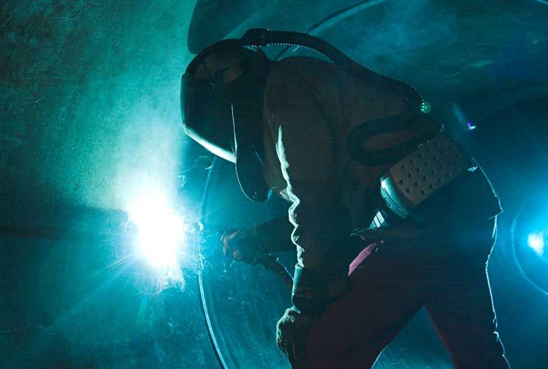
* Concentrations of shielding gas may build up and displace oxygen when welding in confined areas
🛈 More information
-
Filler metal
Filler metal
A filler metal is a metal added in the making of a joint through welding, brazing, or soldering. Four types of filler metals exist-covered electrodes, bare electrode wire or rod, tubular electrode wire and welding fluxes. Sometimes nonconsumable electrodes are included as well, but since these metals are not consumed by the welding process, they are normally excluded.
Usage
Covered electrodes
Covered electrodes are used extensively in shielded metal arc welding and are a major factor in that method's popularity.
Bare electrode wires
Bare electrode wires are used in gas metal arc welding and bare electrode rods are used in gas tungsten arc welding.
Tubular electrode wires
Tubular electrode wire is used in flux-cored arc welding.
Welding fluxes
Welding fluxes are used in submerged arc welding.
-
Amorphous brazing foil
Amorphous brazing foil
The filler metal (FM) alloys that can be produced as amorphous brazing foils (ABF) are eutectic compositions formed by transition metals such as nickel, iron, copper, etc., in combination with metalloids, such as silicon, boron and phosphorus. In conventional crystalline state, all these materials are inherently brittle and cannot be produced in continuous forms such as foil, wire, etc. Therefore, they were available only as powders, pastes, or their derivates. On the other hand, the very presence of metalloids at or near the eutectic concentration promotes the rapid solidification (RS) conversion of such alloys into a ductile amorphous foil.
Production
The production of amorphous alloys requires a manufacturing technology that operates on the basis of the necessary cooling rates, which is known as rapid solidification, or melt spinning technology. Amorphous structures are characterized by the absence of a crystal lattice or a long range order. With this random, spatially uniform arrangement of the constituent atoms, their structure is similar to that of liquids. The nature of this production process is the reason why amorphous alloys are offered only in the form of thin, ductile metal foils. Subsequently, tapes, parts and premorms can be made by e.g. slitting, cutting, stamping and etching.
Properties
Amorphous brazing foils are compositionally much more uniform even after crystallization, they melt over a narrow temperature range under transient heating. This is a consequence of the shorter distances over which atoms of different elements have to diffuse in order to form a uniform liquid phase. The resulting instant melting and their superior flow characteristic is only one of the important features of ABFs. The absence of the residual organic solvent bases evident in powder paste/tapes correspondingly eliminates soot formation and furnace fouling. The low level of gaseous impurities in ABFs, due to the specific characteristics of its production technology, is an attractive feature for vacuum furnace brazing.
Usage
ABFs are available as strip with a width from 0.5mm to 125mm and a thickness from 20µm to 50µm. Preforms can be easily produced by using punch and die, cutting/slitting, photochemical etching, and other methods. It is simple to use foils and preforms at automatic production and assembling steps. The use of foils and preforms reduces waste and enhances manufacturing efficiency. Drying and evaporation operations, which are required with powder/paste and tape forms, are not necessary. The optimal amount of brazing material can be easily applied to the component and, in just one heating cycle, ABFs create uniform braze joints of outstanding quality.
🛈 More information
WIG-MAG-Plasma-Equipment
Our range of products:
- MIG/MAG welder, all types, gas-cooled, water-cooled
- WIG/TIG welder, all types, gas-cooled, water-cooled
- MIG/MAG equipment and expendables (electric- and gasjet)
- WIG/TIG equipment and expendables
- workstation-equipment (forceps, WIG-bonnets, mirrors)
- automatic-hardhat (+equipment)
- thermal- and propanequipment, air regulator, burner
- siliconfree welding-spray, Biomat-cutting-spray
- pickling-paste, pickling-brushes, solder
- protective goggles, eyeglass lenses, safety glass
- filter lenses, clear glass
- electrode drying ovens, rod holder, cutting- and grinding-wheels steel + inox
- protective curtains (+equipment), lamellae-curtains
- leather aprons, gloves, protective gloves, skin-protection-lotion
- wolfram welding electrode
- adapters, scratch brush (VA) + steel
-
Welding
Welding
Welding is a fabrication process that joins materials, usually metals or thermoplastics, by causing coalescence. This is often done by melting the workpieces and adding a filler material to form a pool of molten material (the weld puddle) that cools to become a strong joint, with pressure sometimes used in conjunction with heat, or by itself, to produce the weld. This is in contrast with soldering and brazing, which involve melting a lower-melting-point material between the workpieces to form a bond between them, without melting the workpieces.
Many different energy sources can be used for welding, including a gas flame, an electric arc, a laser, an electron beam, friction, and ultrasound. While often an industrial process, welding can be done in many different environments, including open air, underwater and in outer space. Regardless of location, however, welding remains dangerous, and precautions must be taken to avoid burns, electric shock, eye damage, poisonous fumes, and overexposure to ultraviolet light.
Until the end of the 19th century, the only welding process was forge welding, which blacksmiths had used for centuries to join metals by heating and pounding them. Arc welding and oxyfuel welding were among the first processes to develop late in the century, and resistance welding followed soon after. Welding technology advanced quickly during the early 20th century as World War I and World War II drove the demand for reliable and inexpensive joining methods. Following the wars, several modern welding techniques were developed, including manual methods like shielded metal arc welding, now one of the most popular welding methods, as well as semi-automatic and automatic processes such as gas metal arc welding, submerged arc welding, flux-cored arc welding and electroslag welding. Developments continued with the invention of laser beam welding and electron beam welding in the latter half of the century. Today, the science continues to advance. Robot welding is becoming more commonplace in industrial settings, and researchers continue to develop new welding methods and gain greater understanding of weld quality and properties.
History
The history of joining metals goes back several millennia, with the earliest examples of welding from the Bronze Age and the Iron Age in Europe and the Middle East. Welding was used in the construction of the Iron pillar in Delhi, India, erected about 310 and weighing 5.4 metric tons. The Middle Ages brought advances in forge welding, in which blacksmiths pounded heated metal repeatedly until bonding occurred. In 1540, Vannoccio Biringuccio published De la pirotechnia, which includes descriptions of the forging operation. Renaissance craftsmen were skilled in the process, and the industry continued to grow during the following centuries. Welding, however, was transformed during the 19th century-in 1800, Sir Humphry Davy discovered the electric arc, and advances in arc welding continued with the inventions of metal electrodes by a Russian, Nikolai Slavyanov, and an American, C. L. Coffin in the late 1800s, even as carbon arc welding, which used a carbon electrode, gained popularity. Around 1900, A. P. Strohmenger released a coated metal electrode in Britain, which gave a more stable arc, and in 1919, alternating current welding was invented by C. J. Holslag, but did not become popular for another decade.
Resistance welding was also developed during the final decades of the 19th century, with the first patents going to Elihu Thomson in 1885, who produced further advances over the next 15 years. Thermite welding was invented in 1893, and around that time, another process, oxyfuel welding, became well established. Acetylene was discovered in 1836 by Edmund Davy, but its use was not practical in welding until about 1900, when a suitable blowtorch was developed. At first, oxyfuel welding was one of the more popular welding methods due to its portability and relatively low cost. As the 20th century progressed, however, it fell out of favor for industrial applications. It was largely replaced with arc welding, as metal coverings (known as flux) for the electrode that stabilize the arc and shield the base material from impurities continued to be developed.
World War I caused a major surge in the use of welding processes, with the various military powers attempting to determine which of the several new welding processes would be best. The British primarily used arc welding, even constructing a ship, the Fulagar, with an entirely welded hull. Arc welding was first applied to aircraft during the war as well, as some German airplane fuselages were constructed using the process. Also noteworthy is the first welded road bridge in the world built across the river Sludwia Maurzyce near Lowicz, Poland) in 1929, but designed by Stefan Bryla of the Warsaw University of Technology in 1927.
During the 1920s, major advances were made in welding technology, including the introduction of automatic welding in 1920, in which electrode wire was fed continuously. Shielding gas became a subject receiving much attention, as scientists attempted to protect welds from the effects of oxygen and nitrogen in the atmosphere. Porosity and brittleness were the primary problems, and the solutions that developed included the use of hydrogen, argon, and helium as welding atmospheres. During the following decade, further advances allowed for the welding of reactive metals like aluminum and magnesium. This, in conjunction with developments in automatic welding, alternating current, and fluxes fed a major expansion of arc welding during the 1930s and then during World War II.
During the middle of the century, many new welding methods were invented. 1930 saw the release of stud welding, which soon became popular in shipbuilding and construction. Submerged arc welding was invented the same year, and continues to be popular today. Gas tungsten arc welding, after decades of development, was finally perfected in 1941, and gas metal arc welding followed in 1948, allowing for fast welding of non-ferrous materials but requiring expensive shielding gases. Shielded metal arc welding was developed during the 1950s, using a flux coated consumable electrode, and it quickly became the most popular metal arc welding process. In 1957, the flux-cored arc welding process debuted, in which the self-shielded wire electrode could be used with automatic equipment, resulting in greatly increased welding speeds, and that same year, plasma arc welding was invented. Electroslag welding was introduced in 1958, and it was followed by its cousin, electrogas welding, in 1961.
Other recent developments in welding include the 1958 breakthrough of electron beam welding, making deep and narrow welding possible through the concentrated heat source. Following the invention of the laser in 1960, laser beam welding debuted several decades later, and has proved to be especially useful in high-speed, automated welding. Both of these processes, however, continue to be quite expensive due the high cost of the necessary equipment, and this has limited their applications.
Processes
Arc
These processes use a welding power supply to create and maintain an electric arc between an electrode and the base material to melt metals at the welding point. They can use either direct (DC) or alternating (AC) current, and consumable or non-consumable electrodes. The welding region is sometimes protected by some type of inert or semi-inert gas, known as a shielding gas, and filler material is sometimes used as well.
Power supplies
To supply the electrical energy necessary for arc welding processes, a number of different power supplies can be used. The most common classification is constant current power supplies and constant voltage power supplies. In arc welding, the length of the arc is directly related to the voltage, and the amount of heat input is related to the current. Constant current power supplies are most often used for manual welding processes such as gas tungsten arc welding and shielded metal arc welding, because they maintain a relatively constant current even as the voltage varies. This is important because in manual welding, it can be difficult to hold the electrode perfectly steady, and as a result, the arc length and thus voltage tend to fluctuate. Constant voltage power supplies hold the voltage constant and vary the current, and as a result, are most often used for automated welding processes such as gas metal arc welding, flux cored arc welding, and submerged arc welding. In these processes, arc length is kept constant, since any fluctuation in the distance between the wire and the base material is quickly rectified by a large change in current. For example, if the wire and the base material get too close, the current will rapidly increase, which in turn causes the heat to increase and the tip of the wire to melt, returning it to its original separation distance.
The type of current used in arc welding also plays an important role in welding. Consumable electrode processes such as shielded metal arc welding and gas metal arc welding generally use direct current, but the electrode can be charged either positively or negatively. In welding, the positively charged anode will have a greater heat concentration, and as a result, changing the polarity of the electrode has an impact on weld properties. If the electrode is positively charged, the base metal will be hotter, increasing weld penetration and welding speed. Alternatively, a negatively charged electrode results in more shallow welds. Nonconsumable electrode processes, such as gas tungsten arc welding, can use either type of direct current, as well as alternating current. However, with direct current, because the electrode only creates the arc and does not provide filler material, a positively charged electrode causes shallow welds, while a negatively charged electrode makes deeper welds. Alternating current rapidly moves between these two, resulting in medium-penetration welds. One disadvantage of AC, the fact that the arc must be re-ignited after every zero crossing, has been addressed with the invention of special power units that produce a square wave pattern instead of the normal sine wave, making rapid zero crossings possible and minimizing the effects of the problem.
Processes
One of the most common types of arc welding is shielded metal arc welding (SMAW), which is also known as manual metal arc welding (MMA) or stick welding. Electric current is used to strike an arc between the base material and consumable electrode rod, which is made of steel and is covered with a flux that protects the weld area from oxidation and contamination by producing CO2 gas during the welding process. The electrode core itself acts as filler material, making a separate filler unnecessary.
The process is versatile and can be performed with relatively inexpensive equipment, making it well suited to shop jobs and field work. An operator can become reasonably proficient with a modest amount of training and can achieve mastery with experience. Weld times are rather slow, since the consumable electrodes must be frequently replaced and because slag, the residue from the flux, must be chipped away after welding. Furthermore, the process is generally limited to welding ferrous materials, though special electrodes have made possible the welding of cast iron, nickel, aluminium, copper, and other metals. Inexperienced operators may find it difficult to make good out-of-position welds with this process.
Gas metal arc welding (GMAW), also known as metal inert gas or MIG welding, is a semi-automatic or automatic process that uses a continuous wire feed as an electrode and an inert or semi-inert gas mixture to protect the weld from contamination. As with SMAW, reasonable operator proficiency can be achieved with modest training. Since the electrode is continuous, welding speeds are greater for GMAW than for SMAW. Also, the smaller arc size compared to the shielded metal arc welding process makes it easier to make out-of-position welds (e.g., overhead joints, as would be welded underneath a structure).
The equipment required to perform the GMAW process is more complex and expensive than that required for SMAW, and requires a more complex setup procedure. Therefore, GMAW is less portable and versatile, and due to the use of a separate shielding gas, is not particularly suitable for outdoor work. However, owing to the higher average rate at which welds can be completed, GMAW is well suited to production welding. The process can be applied to a wide variety of metals, both ferrous and non-ferrous.
A related process, flux-cored arc welding (FCAW), uses similar equipment but uses wire consisting of a steel electrode surrounding a powder fill material. This cored wire is more expensive than the standard solid wire and can generate fumes and/or slag, but it permits even higher welding speed and greater metal penetration.
Gas tungsten arc welding (GTAW), or tungsten inert gas (TIG) welding (also sometimes erroneously referred to as heliarc welding), is a manual welding process that uses a nonconsumable tungsten electrode, an inert or semi-inert gas mixture, and a separate filler material. Especially useful for welding thin materials, this method is characterized by a stable arc and high quality welds, but it requires significant operator skill and can only be accomplished at relatively low speeds.
GTAW can be used on nearly all weldable metals, though it is most often applied to stainless steel and light metals. It is often used when quality welds are extremely important, such as in bicycle, aircraft and naval applications. A related process, plasma arc welding, also uses a tungsten electrode but uses plasma gas to make the arc. The arc is more concentrated than the GTAW arc, making transverse control more critical and thus generally restricting the technique to a mechanized process. Because of its stable current, the method can be used on a wider range of material thicknesses than can the GTAW process, and furthermore, it is much faster. It can be applied to all of the same materials as GTAW except magnesium, and automated welding of stainless steel is one important application of the process. A variation of the process is plasma cutting, an efficient steel cutting process.
Submerged arc welding (SAW) is a high-productivity welding method in which the arc is struck beneath a covering layer of flux. This increases arc quality, since contaminants in the atmosphere are blocked by the flux. The slag that forms on the weld generally comes off by itself, and combined with the use of a continuous wire feed, the weld deposition rate is high. Working conditions are much improved over other arc welding processes, since the flux hides the arc and almost no smoke is produced. The process is commonly used in industry, especially for large products and in the manufacture of welded pressure vessels. Other arc welding processes include atomic hydrogen welding, carbon arc welding, electroslag welding, electrogas welding, and stud arc welding.
Gas
The most common gas welding process is oxyfuel welding, also known as oxyacetylene welding. It is one of the oldest and most versatile welding processes, but in recent years it has become less popular in industrial applications. It is still widely used for welding pipes and tubes, as well as repair work. It is also frequently well-suited, and favored, for fabricating some types of metal-based artwork. Oxyfuel equipment is versatile, lending itself not only to some sorts of iron or steel welding but also to brazing, braze-welding, metal heating (for bending and forming), and also oxyfuel cutting.
The equipment is relatively inexpensive and simple, generally employing the combustion of acetylene in oxygen to produce a welding flame temperature of about 3100 °C. The flame, since it is less concentrated than an electric arc, causes slower weld cooling, which can lead to greater residual stresses and weld distortion, though it eases the welding of high alloy steels. A similar process, generally called oxyfuel cutting, is used to cut metals. Other gas welding methods, such as air acetylene welding, oxygen hydrogen welding, and pressure gas welding are quite similar, generally differing only in the type of gases used. A water torch is sometimes used for precision welding of small items such as jewelry. Gas welding is also used in plastic welding, though the heated substance is air, and the temperatures are much lower.
Resistance
Resistance welding involves the generation of heat by passing current through the resistance caused by the contact between two or more metal surfaces. Small pools of molten metal are formed at the weld area as high current (1000-100,000 A) is passed through the metal. In general, resistance welding methods are efficient and cause little pollution, but their applications are somewhat limited and the equipment cost can be high.
Spot welding is a popular resistance welding method used to join overlapping metal sheets of up to 3 mm thick. Two electrodes are simultaneously used to clamp the metal sheets together and to pass current through the sheets. The advantages of the method include efficient energy use, limited workpiece deformation, high production rates, easy automation, and no required filler materials. Weld strength is significantly lower than with other welding methods, making the process suitable for only certain applications. It is used extensively in the automotive industry-ordinary cars can have several thousand spot welds made by industrial robots. A specialized process, called shot welding, can be used to spot weld stainless steel.
Like spot welding, seam welding relies on two electrodes to apply pressure and current to join metal sheets. However, instead of pointed electrodes, wheel-shaped electrodes roll along and often feed the workpiece, making it possible to make long continuous welds. In the past, this process was used in the manufacture of beverage cans, but now its uses are more limited. Other resistance welding methods include flash welding, projection welding, and upset welding.
Energy beam
Energy beam welding methods, namely laser beam welding and electron beam welding, are relatively new processes that have become quite popular in high production applications. The two processes are quite similar, differing most notably in their source of power. Laser beam welding employs a highly focused laser beam, while electron beam welding is done in a vacuum and uses an electron beam. Both have a very high energy density, making deep weld penetration possible and minimizing the size of the weld area. Both processes are extremely fast, and are easily automated, making them highly productive. The primary disadvantages are their very high equipment costs (though these are decreasing) and a susceptibility to thermal cracking. Developments in this area include laser-hybrid welding, which uses principles from both laser beam welding and arc welding for even better weld properties.
Solid-state
Like the first welding process, forge welding, some modern welding methods do not involve the melting of the materials being joined. One of the most popular, ultrasonic welding, is used to connect thin sheets or wires made of metal or thermoplastic by vibrating them at high frequency and under high pressure. The equipment and methods involved are similar to that of resistance welding, but instead of electric current, vibration provides energy input. Welding metals with this process does not involve melting the materials; instead, the weld is formed by introducing mechanical vibrations horizontally under pressure. When welding plastics, the materials should have similar melting temperatures, and the vibrations are introduced vertically. Ultrasonic welding is commonly used for making electrical connections out of aluminum or copper, and it is also a very common polymer welding process.
Another common process, explosion welding, involves the joining of materials by pushing them together under extremely high pressure. The energy from the impact plasticizes the materials, forming a weld, even though only a limited amount of heat is generated. The process is commonly used for welding dissimilar materials, such as the welding of aluminum with steel in ship hulls or compound plates. Other solid-state welding processes include co-extrusion welding, cold welding, diffusion welding, friction welding (including friction stir welding), high frequency welding, hot pressure welding, induction welding, and roll welding.
Geometry
Welds can be geometrically prepared in many different ways. The five basic types of weld joints are the butt joint, lap joint, corner joint, edge joint, and T-joint. Other variations exist as well-for example, double-V preparation joints are characterized by the two pieces of material each tapering to a single center point at one-half their height. Single-U and double-U preparation joints are also fairly common-instead of having straight edges like the single-V and double-V preparation joints, they are curved, forming the shape of a U. Lap joints are also commonly more than two pieces thick-depending on the process used and the thickness of the material, many pieces can be welded together in a lap joint geometry.
Often, particular joint designs are used exclusively or almost exclusively by certain welding processes. For example, resistance spot welding, laser beam welding, and electron beam welding are most frequently performed on lap joints. However, some welding methods, like shielded metal arc welding, are extremely versatile and can weld virtually any type of joint. Additionally, some processes can be used to make multipass welds, in which one weld is allowed to cool, and then another weld is performed on top of it. This allows for the welding of thick sections arranged in a single-V preparation joint, for example.
After welding, a number of distinct regions can be identified in the weld area. The weld itself is called the fusion zone-more specifically, it is where the filler metal was laid during the welding process. The properties of the fusion zone depend primarily on the filler metal used, and its compatibility with the base materials. It is surrounded by the heat-affected zone, the area that had its microstructure and properties altered by the weld. These properties depend on the base material's behavior when subjected to heat. The metal in this area is often weaker than both the base material and the fusion zone, and is also where residual stresses are found.
Quality
Most often, the major metric used for judging the quality of a weld is its strength and the strength of the material around it. Many distinct factors influence this, including the welding method, the amount and concentration of energy input, the base material, the filler material, the flux material, the design of the joint, and the interactions between all these factors. To test the quality of a weld, either destructive or nondestructive testing methods are commonly used to verify that welds are defect-free, have acceptable levels of residual stresses and distortion, and have acceptable heat-affected zone (HAZ) properties. Welding codes and specifications exist to guide welders in proper welding technique and in how to judge the quality of welds.
Heat-affected zone
The effects of welding on the material surrounding the weld can be detrimental-depending on the materials used and the heat input of the welding process used, the HAZ can be of varying size and strength. The thermal diffusivity of the base material plays a large role-if the diffusivity is high, the material cooling rate is high and the HAZ is relatively small. Conversely, a low diffusivity leads to slower cooling and a larger HAZ. The amount of heat injected by the welding process plays an important role as well, as processes like oxyacetylene welding have an unconcentrated heat input and increase the size of the HAZ. Processes like laser beam welding give a highly concentrated, limited amount of heat, resulting in a small HAZ. Arc welding falls between these two extremes, with the individual processes varying somewhat in heat input.
To calculate the heat input for arc welding procedures, the following formula can be used:
Q = \left(\frac{V \times I \times 60}{S \times 1000} \right) \times \mathit{Efficiency}
where Q = heat input (kJ/mm), V = voltage (V), I = current (A), and S = welding speed (mm/min). The efficiency is dependent on the welding process used, with shielded metal arc welding having a value of 0.75, gas metal arc welding and submerged arc welding, 0.9, and gas tungsten arc welding, 0.8.
Distortion and cracking
Welding methods that involve the melting of metal at the site of the joint necessarily are prone to shrinkage as the heated metal cools. Shrinkage, in turn, can introduce residual stresses and both longitudinal and rotational distortion. Distortion can pose a major problem, since the final product is not the desired shape. To alleviate rotational distortion, the workpieces can be offset, so that the welding results in a correctly shaped piece. Other methods of limiting distortion, such as clamping the workpieces in place, cause the buildup of residual stress in the heat-affected zone of the base material. These stresses can reduce the strength of the base material, and can lead to catastrophic failure through cold cracking, as in the case of several of the Liberty ships. Cold cracking is limited to steels, and is associated with the formation of martensite as the weld cools. The cracking occurs in the heat-affected zone of the base material. To reduce the amount of distortion and residual stresses, the amount of heat input should be limited, and the welding sequence used should not be from one end directly to the other, but rather in segments. The other type of cracking, hot cracking or solidification cracking, can occur with all metals, and happens in the fusion zone of a weld. To diminish the probability of this type of cracking, excess material restraint should be avoided, and a proper filler material should be utilized.
Weldability
The quality of a weld is also dependent on the combination of materials used for the base material and the filler material. Not all metals are suitable for welding, and not all filler metals work well with acceptable base materials.
Steels
The weldability of steels is inversely proportional to a property known as the hardenability of the steel, which measures the probability of forming martensite during welding or heat treatment. The hardenability of steel depends on its chemical composition, with greater quantities of carbon and other alloying elements resulting in a higher hardenability and thus a lower weldability. In order to be able to judge alloys made up of many distinct materials, a measure known as the equivalent carbon content is used to compare the relative weldabilities of different alloys by comparing their properties to a plain carbon steel. The effect on weldability of elements like chromium and vanadium, while not as great as carbon, is more significant than that of copper and nickel, for example. As the equivalent carbon content rises, the weldability of the alloy decreases. The disadvantage to using plain carbon and low-alloy steels is their lower strength-there is a trade-off between material strength and weldability. High strength, low-alloy steels were developed especially for welding applications during the 1970s, and these generally easy to weld materials have good strength, making them ideal for many welding applications.
Stainless steels, because of their high chromium content, tend to behave differently with respect to weldability than other steels. Austenitic grades of stainless steels tend to be the most weldable, but they are especially susceptible to distortion due to their high coefficient of thermal expansion. Some alloys of this type are prone to cracking and reduced corrosion resistance as well. Hot cracking is possible if the amount of ferrite in the weld is not controlled-to alleviate the problem, an electrode is used that deposits a weld metal containing a small amount of ferrite. Other types of stainless steels, such as ferritic and martensitic stainless steels, are not as easily welded, and must often be preheated and welded with special electrodes.
Aluminum
The weldability of aluminum alloys varies significantly, depending on the chemical composition of the alloy used. Aluminum alloys are susceptible to hot cracking, and to combat the problem, welders increase the welding speed to lower the heat input. Preheating reduces the temperature gradient across the weld zone and thus helps reduce hot cracking, but it can reduce the mechanical properties of the base material and should not be used when the base material is restrained. The design of the joint can be changed as well, and a more compatible filler alloy can be selected to decrease the likelihood of hot cracking. Aluminum alloys should also be cleaned prior to welding, with the goal of removing all oxides, oils, and loose particles from the surface to be welded. This is especially important because of an aluminum weld's susceptibility to porosity due to hydrogen and dross due to oxygen.
Unusual conditions
While many welding applications are done in controlled environments such as factories and repair shops, some welding processes are commonly used in a wide variety of conditions, such as open air, underwater, and vacuums (such as space). In open-air applications, such as construction and outdoors repair, shielded metal arc welding is the most common process. Processes that employ inert gases to protect the weld cannot be readily used in such situations, because unpredictable atmospheric movements can result in a faulty weld. Shielded metal arc welding is also often used in underwater welding in the construction and repair of ships, offshore platforms, and pipelines, but others, such as flux cored arc welding and gas tungsten arc welding, are also common. Welding in space is also possible-it was first attempted in 1969 by Russian cosmonauts, when they performed experiments to test shielded metal arc welding, plasma arc welding, and electron beam welding in a depressurized environment. Further testing of these methods was done in the following decades, and today researchers continue to develop methods for using other welding processes in space, such as laser beam welding, resistance welding, and friction welding. Advances in these areas could prove indispensable for projects like the construction of the International Space Station, which will likely rely heavily on welding for joining in space the parts that were manufactured on Earth.
Safety issues
Welding, without the proper precautions, can be a dangerous and unhealthy practice. However, with the use of new technology and proper protection, risks of injury and death associated with welding can be greatly reduced. Because many common welding procedures involve an open electric arc or flame, the risk of burns is significant. To prevent them, welders wear personal protective equipment in the form of heavy leather gloves and protective long sleeve jackets to avoid exposure to extreme heat and flames. Additionally, the brightness of the weld area leads to a condition called arc eye in which ultraviolet light causes inflammation of the cornea and can burn the retinas of the eyes. Goggles and welding helmets with dark face plates are worn to prevent this exposure, and in recent years, new helmet models have been produced that feature a face plate that self-darkens upon exposure to high amounts of UV light. To protect bystanders, translucent welding curtains often surround the welding area. These curtains, made of a polyvinyl chloride plastic film, shield nearby workers from exposure to the UV light from the electric arc, but should not be used to replace the filter glass used in helmets.
Welders are also often exposed to dangerous gases and particulate matter. Processes like flux-cored arc welding and shielded metal arc welding produce smoke containing particles of various types of oxides, which in some cases can lead to medical conditions like metal fume fever. The size of the particles in question tends to influence the toxicity of the fumes, with smaller particles presenting a greater danger. Additionally, many processes produce fumes and various gases, most commonly carbon dioxide, ozone and heavy metals, that can prove dangerous without proper ventilation and training. Furthermore, because the use of compressed gases and flames in many welding processes poses an explosion and fire risk, some common precautions include limiting the amount of oxygen in the air and keeping combustible materials away from the workplace.
Welding fume extractors are often used to remove the fume from the source and filter the fumes through a HEPA filter.
Costs and trends
As an industrial process, the cost of welding plays a crucial role in manufacturing decisions. Many different variables affect the total cost, including equipment cost, labor cost, material cost, and energy cost. Depending on the process, equipment cost can vary, from inexpensive for methods like shielded metal arc welding and oxyfuel welding, to extremely expensive for methods like laser beam welding and electron beam welding. Because of their high cost, they are only used in high production operations. Similarly, because automation and robots increase equipment costs, they are only implemented when high production is necessary. Labor cost depends on the deposition rate (the rate of welding), the hourly wage, and the total operation time, including both time welding and handling the part. The cost of materials includes the cost of the base and filler material, and the cost of shielding gases. Finally, energy cost depends on arc time and welding power demand.
For manual welding methods, labor costs generally make up the vast majority of the total cost. As a result, many cost-savings measures are focused on minimizing the operation time. To do this, welding procedures with high deposition rates can be selected, and weld parameters can be fine-tuned to increase welding speed. Also, removal of welding spatters generated during welding process is highly labor intensive and time consuming. Implementation of Welding Anti Spatter & Flux which is safe & non-polluting is considered as a welcome change in cost cutting & weld joint quality improvement measures. Mechanization and automatization are often implemented to reduce labor costs, but this frequently increases the cost of equipment and creates additional setup time. Material costs tend to increase when special properties are necessary, and energy costs normally do not amount to more than several percent of the total welding cost.
In recent years, in order to minimize labor costs in high production manufacturing, industrial welding has become increasingly more automated, most notably with the use of robots in resistance spot welding (especially in the automotive industry) and in arc welding. In robot welding, mechanized devices both hold the material and perform the weld, and at first, spot welding was its most common application. But robotic arc welding has been increasing in popularity as technology has advanced. Other key areas of research and development include the welding of dissimilar materials (such as steel and aluminum, for example) and new welding processes, such as friction stir, magnetic pulse, conductive heat seam, and laser-hybrid welding. Furthermore, progress is desired in making more specialized methods like laser beam welding practical for more applications, such as in the aerospace and automotive industries. Researchers also hope to better understand the often unpredictable properties of welds, especially microstructure, residual stresses, and a weld's tendency to crack or deform.
-
Welding power supply
Welding power supply
A welding power supply is a device that provides an electric current to perform welding. Welding usually requires high current (over 80 amperes) and it can need above 12,000 amps in spot welding. Low current can also be used; welding two razor blades together at 5 amps with gas tungsten arc welding is a good example. A welding power supply can be as simple as a car battery and as sophisticated as a modern machine based on silicon controlled rectifier technology with additional logic to assist in the welding process.
Classification
Welding machines are usually classified as constant current (CC) or constant voltage (CV); a constant current machine will vary its output voltage to maintain a steady current while a constant voltage machine will fluctuate its output current to maintain a set voltage. Shielded metal arc welding will use a constant current source and gas metal arc welding and flux-cored arc welding typically use constant voltage sources but constant current is also possible with a voltage sensing wire feeder.
The nature of the CV machine is required by gas metal arc welding and flux-cored arc welding because the welder is not able to control the arc length manually. If a welder attempted to use a CV machine to weld with shielded metal arc welding the small fluctuations in the arc distance would cause wide fluctuations in the machine's output. With a CC machine the welder can count on a fixed number of amps reaching the material to be welded regardless of the arc distance but too much distance will cause poor welding.
Machine construction
Most welding machines are of the following designs:
Transformer
A transformer style welding machine converts the high voltage and low current electricity from the utility into a high current and low voltage, typically between 17 to 45 volts and 190 to 590 amps. This type of machine typically allows the welder to select the output current by either moving the core of the transformer in and out of the magnetic field or by allowing the welder to select from a set of taps on the transformer. These machines are typically the least expensive to purchase for hobbyist use.
Generator and alternator
Welding machines may also use generators or alternators to convert mechanical energy into electrical energy. Modern machines of this type are usually driven by an internal combustion engine but some older machines may also use an electric motor to drive the alternator or generator. In this configuration the utility power is converted first into mechanical energy then back into electrical energy to achieve the step-down effect similar to a transformer. Because the output of the generator can be direct current, these older machines can produce DC from AC without any need for rectifiers of any type.
Inverter
Since the advent of high-power semiconductors such as the IGBT, it is now possible to build a switching power supply capable of coping with the high loads of arc welding. These are known as inverter welding units. These supplies generally convert utility power to high voltage and store this energy in a capacitor bank; a microprocessor controller then switches this energy into a second transformer as needed to produce the desired welding current. The switching frequency is very high - typically 10,000 Hz or higher. The high frequency inverter-based welding machines can be more efficient and have better control than non-inverter welding machines.
The IGBTs in an inverter based machine are controlled by a microcontroller, so the electrical characteristics of the welding power can be changed by software in real time updates. Typically the controller software will implement features such as pulsing the welding current, variable ratios and current densities through a welding cycle, variable frequencies, and automatic spot-welding; all of which would be prohibitively expensive in a transformer-based machine but require only program space in software-controlled inverter machine.
🛈 More information
Call us: ☎ 0421 - 60 64 79
Bremer Schweißtechnik GmbH
Wierenstraße 12
28779 Bremen